
Device Configuration
This section will be related to various settings related to or under that Device. To manage this information via https://portal.nexiiot.io, go to the Device menu , then click on the desired Device and select various settings that are displayed separately as information bars in each section as shown in the following figure.
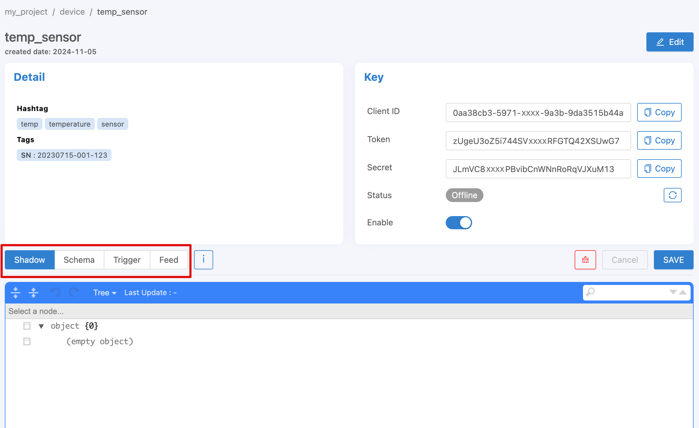
Device Shadow
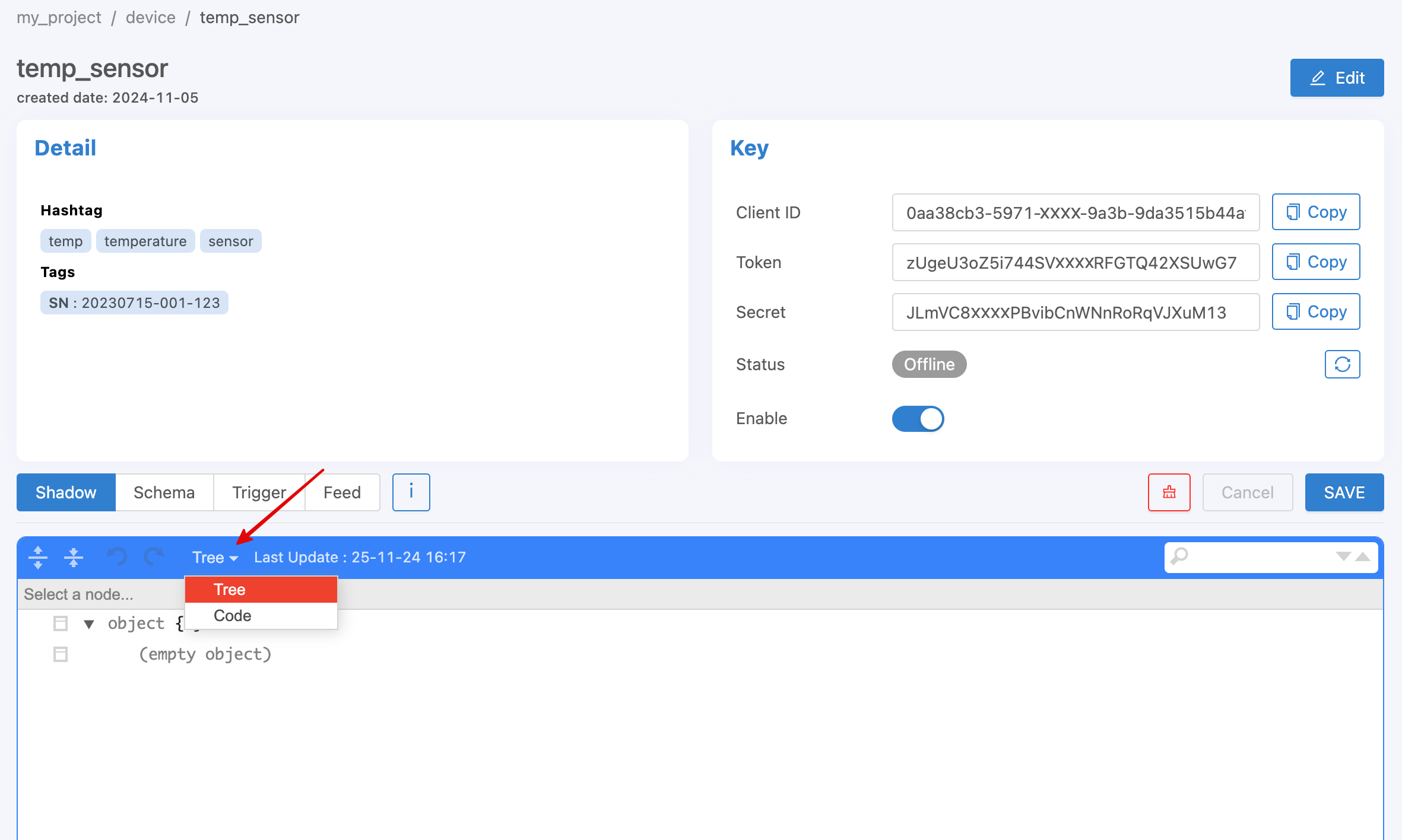
It is a virtual database of the Device. It is a small database that is paired with every Device. It is used to store data that the Device will access and manage, such as data generated by sensors, data on setting up various components of the Device (Device Configuration), etc. In this section, the user can freely design what data it will contain. The data structure will be in the form of JSON (Key-value), as in the following example.
{
        "config": {
                "lastupdate": "2020-06-01",
                "var": {
                        "v1": "a",
                        "v2": true,
                        "v3": 1
                },
                "version": 1
        },
        "enable": true,
        "items": ["a", "b", "c"]
}
If you copy the above example and set the desired device via the Portal page, it will look like this (if you want to copy the code and paste it, change the display type from Tree to Code).
Note
Deleting fields in Shadow via https://portal.nexiiot.io
Saving a Shadow through the Portal web page is a merged save. Therefore, if you want to delete a field from the Shadow, you cannot delete it from the Shadow input field. You must set that field to null. When saving, the system will delete that field from the Shadow.
Shadow Timestamp
The main purpose of shadow writing is to record the data values that occur. Sometimes, instead of the current time value, it is necessary to record the past values. The timestamp of the data point can be set by:
Publish Topic@shadow/data/update
Payload is
{
        "data": {
        "temp": 24.5,
        "Humid": 63.9
        },
        "timestamp": 1684982518000
}
If the feed is set to store data, the time value of the data point will be this timestamp number, instead of the default, which is the current time timestamp. If the specified timestamp is older than the shadow timestamp field, it will not be overwritten to the shadow, but the feed will continue to store data as normal, so we can use this mechanism to update the values in the feed retrospectively.
Shadow Batch Update
We can write many values to the shadow at once. This is useful when we want to write a feed back. The newest value will appear in the shadow. However, if the largest timestamp is less than the shadow's timestamp, the written value will not overwrite the latest value in the shadow, but will still be sent to the store and triggered as usual.
Publish Topic@shadow/data/update
Payload is
{
        "batch" : [
                {"data":{"temp":25.9, "humid":9.6}, "ts":-90000},
                {"data":{"temp":25.3, "humid":9.8}, "ts":-60000},
                {"data":{"temp":24.5, "humid":9.1}, "ts":-30000},
                {"data":{"temp":26.8, "humid":8.2}, "ts":0}
        ],
        "merged": true
}
After writing, there will be a message reply on the topic @private/shadow/batch/update/response for confirmation. Currently, NETPIE sets the max record size to 100. If the command has more records than DeviceShadow, it will not save the value and will return an error on @private/shadow/batch/update/response as well.
Shadow Options
Shadow writing has special options that override certain values from the writing, including:
mergedThis specifies the shadow writing behavior, whether to insert the value into the original value (merged: true) or to overwrite the entire shadow with the specified value (merged: false). If not specified, the default value is merged: true.storeIf set to false , this write operation will not store any feed values.triggerIf set to false , it will specify that this write does not need to run the trigger.
These options are available for both single value and batch writing.
Device Schema
The definition of Device Schema here is the declaration of data structure or various specifications to be used to control Device Shadow to comply with the desired conditions. For devices that have a clear data structure format from the beginning, it is recommended to create a Device Schema of data prepared as a Device Template, allowing the system to help control the data in Device Shadow to comply with the specifications. The things that the system will help do when the Device Schema is declared are as follows:
Defining fields (Properties) that can be saved
Data Validation
Data transformation, such as changing the units of data, etc.
The Device Schema format is JSON, just like Device Shadow, but it cannot be defined independently because it must be in a format that the system can understand and process. Device Schema is declared in JSON format as follows:
{
        "additionalProperties": false,
        "properties": {
                "tempF": {
                        "operation": {
                                "transform": {
                                        "expression": "($.tempC * 1.8) + 32",
                                        "dp": 2
                                }
                        },
                        "type": "number",
                        "autofill": true
                },
                "tempC": {
                        "type": "number"
                },
                "humid": {
                        "type": "number",
                        "minimum": 0,
                        "maximum": 100
                },
                "place": {
                        "type": "string"
                }
        }
}
If you copy the above example and set it to the desired Device via the Portal page, it will look like this (if you want to copy the code and paste it, change the display type from Tree to Code, the same as Shadow).
From the above example, the Device Schema will consist of:
- additionalProperties (boolean):
Permission status for saving data fields to the Device Shadow when the field names do not match those specified in Properties
true=> อนุญาตให้บันทึกลง Device Shadow ได้ทั้งหมดfalse=> อนุญาตให้บันทึกได้เฉพาะส่วนที่มีการกำหนดไว้ใน PropertiesExample: In the Device Schema shown above, the defined Properties are
tempF,tempC,humid, andplace. If the incoming data is{ "temp": 28, "humid": 8.9 }, then IfadditionalProperties : true, both fields will be saved to the Device Shadow. IfadditionalProperties : false, only thehumidfield will be saved to the Device Shadow.- properties (json):
This is a declaration of field names (from the example:
tempF,tempC,humid,place) along with the definition of each field’s properties in JSON format, which is divided into 2 parts:operationFor setting data management in that field, it includes:transformFor data transformation before storageexpressionA formula or method for transforming data values (Data Transformation) before storage, which can be referenced from any field name that has values sent to be saved to Shadow. The reference format is:$.field_nameExample In the Device Schema shown above, the field
tempFis defined with an expression equal to($.tempC * 1.8) + 32. This expression converts the temperature from Celsius to Fahrenheit by multiplying the value by 1.8 and adding 32. The resulting Fahrenheit value is then saved to the Device Shadow. The calculation references the value from thetempCfield and saves the result to thetempFfield.dpor decimal point is used to define how many decimal places the Platform should record for a given value. From the example above,"dp" : 2, if the calculated value oftempFis 78.584, the value that will be saved to the Shadow will be 78.58, and so on.typeThe data type in that field is number, string, boolean, array, object.maximumUse to set the maximum value that the Platform will allow to save for the specified field, typeas number.minimumSpecifies the minimum value that the Platform will allow to save for the specified field, which typeis number.autofillUsed to set the system to automatically write the field values with the original values in Shadow even if no values for the field are sent in for writing. Used in cases where you want to prompt the system to know that the field will have data updated, but the data is not generated from sending values directly, but is calculated from values from other fields sent in. Or in cases where data is set to be saved to Feed (Timeseries Database) and you want every field to have values stored for every time period. If no values are sent in, the system will automatically save them as the original values so that when data is retrieved for use, there will be complete values for every field in each time period.
Example In the Device Schema shown above, the field
tempFhasautofillset. This means thattempFis derived by converting the value of thetempCfield into Fahrenheit. When writing to the Shadow, thetempFfield is not sent explicitly. The system will automatically calculate the value from thetempCfield and save it intotempF. Ifautofillis not set, the user must manually send a dummy value to thetempFfield to trigger the system to recognize the update. Otherwise, the system will not update thetempFfield.
Note
Difference between Expression, Schema and Feed (datatag) definition
Setting expressionboth parts will transform the data values (Data Transformation) before saving as well. However, at Schema, it can reference or calculate with other fields that are passed in. But if it is set expressionat Feed (datatag), it cannot reference values from other fields. It can only use the datatag value of that field to calculate with general constants before saving to Feed.
Caution
Field names specified in Device Schema Properties must only contain letters (az, AZ), numbers (0-9), or Underscore (_). No other special characters can be used, as they will not store data.
The benefits of defining a Device Schema are as follows:
1. Used to validate data type
You can set various values of the data field, such as data type, minimum, maximum. If a variable in a shadow field does not pass the validation condition, that variable will not be saved as if no data was sent. Other variables will continue to be processed.
{
        "additionalProperties": true,
        "properties": {
                "temp": {
                        "type": "number",
                        "minimum": 0,
                        "maximum": 100,
                        "default": 25,
                }
        }
}
However, if the variable passed in has a different type than the one specified in the schema, the system will attempt to convert it to the most suitable format.
Case 1 Wrong type variable is written into a schema variable of type string. The system will automatically convert it to a string, for example:
Variable |
Tranformed Variable |
2 |
"2" |
true |
"true" |
{x: 123} |
"{"x":123}" |
Case 2 Wrong type of variable is written into a schema variable of type number. The system will automatically convert it to number if it can be converted. However, if it cannot be converted, the system will not save the variable.
Variable |
Tranformed Variable |
"2.3" |
2.3 |
true |
1 |
{x: 123} |
Do not save this variable |
Case 3 Wrong type variable is written into a schema variable of boolean type. The system will automatically convert it to boolean. However, if the conversion is not possible or ambiguous, the system will not save the variable.
Variable |
Tranformed Variable |
"TruE" |
true |
"False" |
false |
0 |
false |
1 |
true |
{x: 123} |
Do not save this variable |
2. Use the basic data conversion
You can include a function to convert values before saving. Variable values starting with $. are references to the newly updated values. You can reference them as a dot notation path, as in the following example. $home.bedroom.temp Example of converting units of an incoming sensor value from Celsius to Fahrenheit.
{
        "additionalProperties": true,
        "properties": {
                "temp": {
                        "type": "number",
                        "minimum": 0,
                        "maximum": 100,
                        "operation": {
                                "transform": {
                                        "expression": "$.temp*1.8 + 32"
                                }
                        }
                }
        }
}
Schema Decimal Transform
Referencing old values of variables can use $$. The $. will refer to the newly updated value. For example, it will smooth the value by taking the average weight of the original value and setting the decimal place of the calculated value to 1 place before saving by specifying the field dp or decimal places. For example, if the value dp: 1 is set, if the value passed in or obtained from the calculation is 0.3333333333, the system will convert the value to 0.3 before saving.
{
        "additionalProperties": true,
        "properties": {
                "humid": {
                        "type": "number",
                        "operation": {
                                "transform": {
                                        "expression": "0.9*$$.humid + 0.1*$.humid",
                                        "dp": 1
                                }
                        }
                }
        }
}
Schema Array Transform
The Transform feature has special functions that can be called, including:
concat(array, array)Merge two arraysslice(array, int)Cut the variable by the specified amount. The second field, if negative, will be cut from the back.sort(array, int)Reorders the array. The second field, plus or minus (e.g. -1, 1 ), specifies the sort direction.reverse(array)Reverse the array.
        {
        "properties": {
                "temp": {
                        "operation": {
                                "transform": {
                                        "expression": "$.temp"
                }
        }
        },
        "log": {
                "operation": {
                        "transform": {
                                "expression": "concat($$.log, [$.temp])"
                }
        }
        },
        "log5": {
                "operation": {
                        "transform": {
                                "expression": "slice(concat($$.log5, [$.temp]), -5)"
                }
        }
        },
        "log5R": {
                "operation": {
                        "transform": {
                                "expression": "slice(reverse($$.log5))"
                }
        }
        },
        "top5": {
                "operation": {
                        "transform": {
                                "expression": "slice(sort(concat($$.top5, [$.temp])), -5)"
                }
        }
        },
        "bottom5": {
                "operation": {
                        "transform": {
                                "expression": "slice(sort(concat($$.bottom5, [$.temp]), -1), -5)"
                                }
                        }
                }
        }
}
Device Trigger and Event Hook
It is a part that links changes in various data of the Device to external actions (Event Hook), such as setting up notifications when the Device changes according to the operating conditions that have been set, etc. The operation is divided into 2 parts as follows:
Trigger
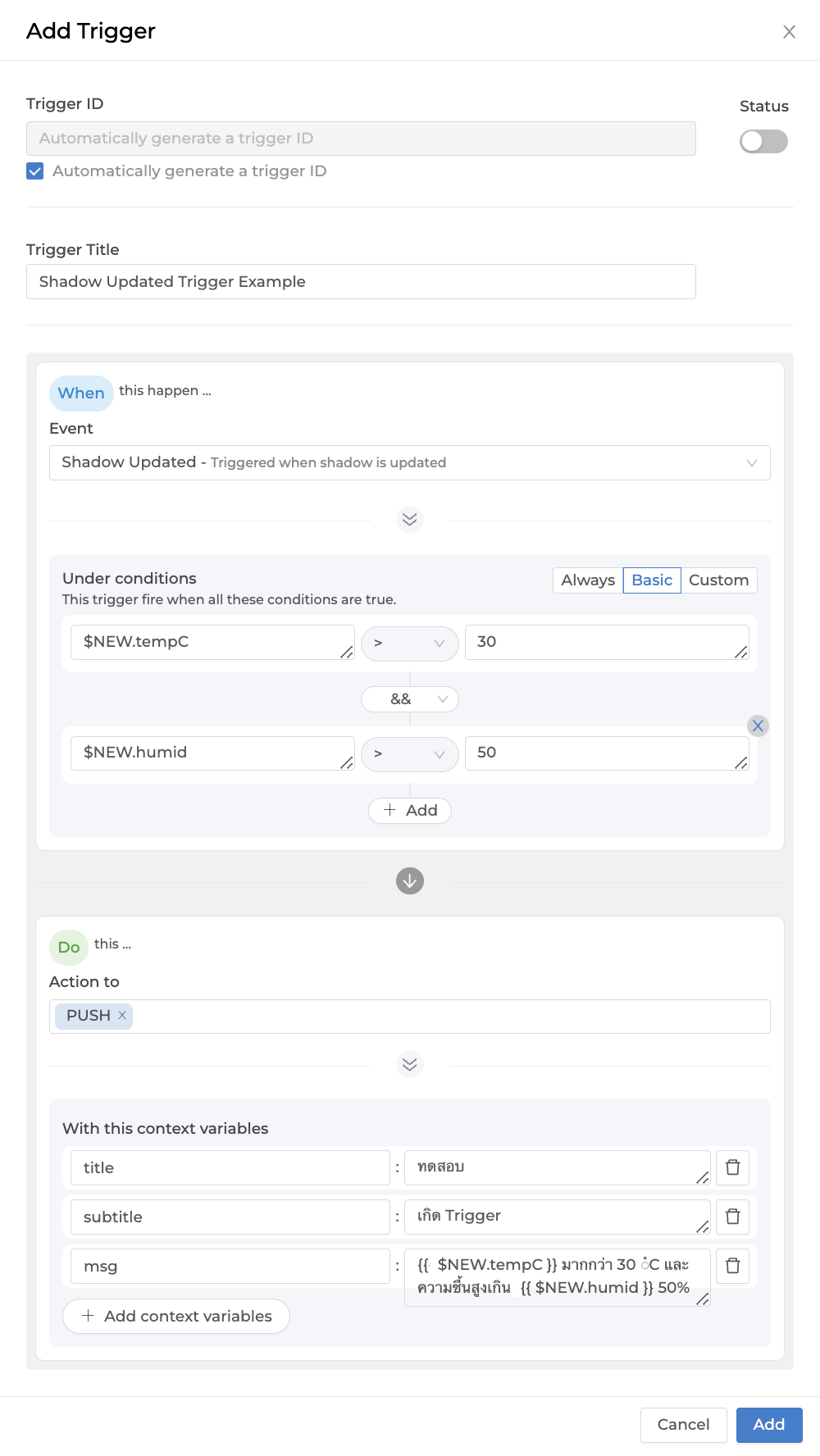
It will be used to set conditions to create a trigger for the system to perform certain actions when the specified conditions are met. Setting up the Device Trigger can be done through the Portal from the tab named Trigger as shown in the following figure.
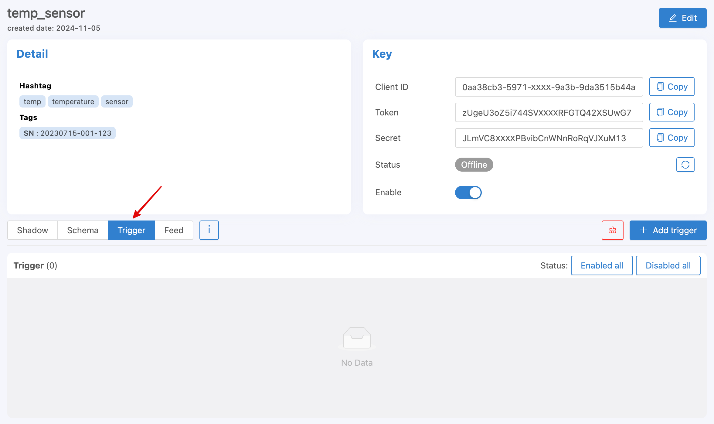
Start creating a Trigger by clicking the Add Trigger button. A screen will appear to set various settings as shown in the following figure.
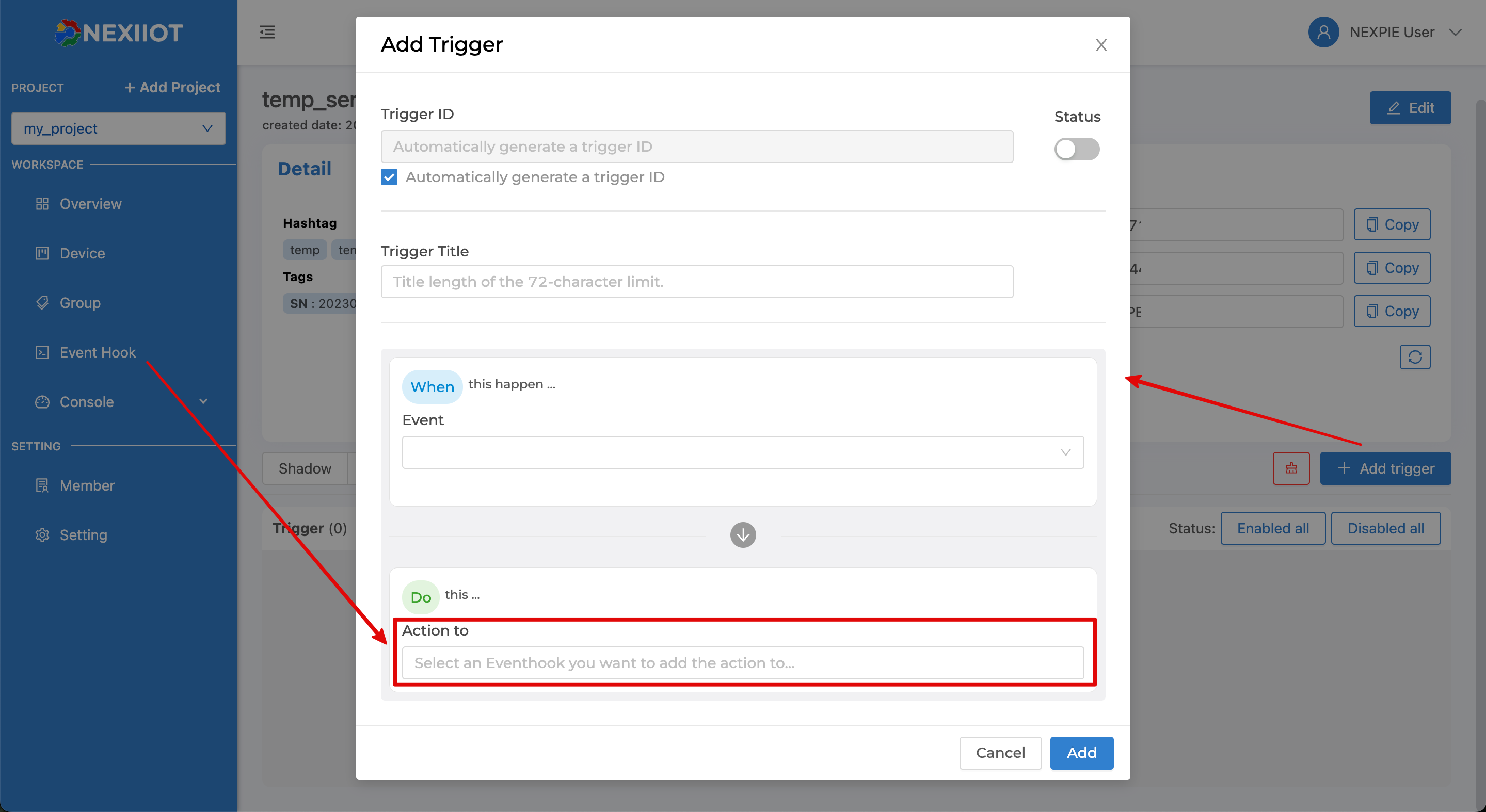
From the figure above, the Trigger data that can be specified are as follows:
Trigger ID |
Trigger ID is automatically generated by the system. If the user wants to set their own, uncheck the "Automatically generate a trigger ID" checkbox and enter the desired code. |
Status |
Trigger On/Off Status |
Trigger Title |
Name or short description of the Trigger |
Event |
|
Under conditions |
|
Action to |
Select the Event Hook that you want to run when the Trigger occurs. The selection list is referenced from the Event Hook menu on the left, and you can select multiple Event Hooks per Trigger. |
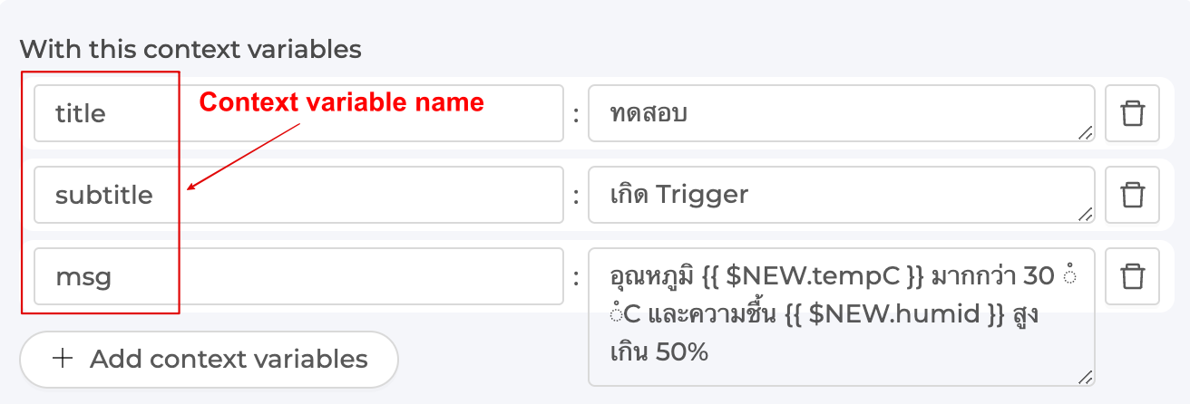
With this context variables |
Declare a variable to be called in the Event Hook by declaring the variable name in the left-hand side box and setting the value in the right-hand side box. The specified value can be a constant, a variable from the Shadow, or a variable from the system that can be called. The reference for use in the Event Hook is: |
Example of setting up a Trigger by selecting Event as Shadow Updated and configuring Under conditions in Basic mode as shown in the following image.
Reference Shadow values in Trigger
To reference the Shadow variable value, it can be called in a Trigger's Condition or Context Variable, with the following syntax:
$CUR.path.of.variableThe most recent updated value ($NEW merge $PREV) starts with $CUR followed by the path as per the Shadow structure.$NEW.path.of.variableNew values sent to update the Shadow start with $NEW followed by the Path structure in the Shadow.$PREV.path.of.variableThe previous value to be updated to the Shadow, starting with $PREV followed by the Path structure in the Shadow.
The difference between $NEW, $CUR, and $PREV in Trigger
Written as an equation, the relationship between the 3 values will be: $CUR = $PREV merge $NEW
Example of references $NEW, $CUR and $PREV
Shadow 1
{
        "f1": "d1",
        "f2": ["A", "B", "C"],
        "f3": { "a1": 1, "a2": 2, "a3": 3 }
}
Write Merge Shadow with this value { "data": { "f2": "A"} }
Shadow 2
{
        "f1": "d1",
        "f2": "A",
        "f3": { "a1": 1, "a2": 2, "a3": 3 }
}
From the JSON above, Shadow 1 represents the Shadow before the update, and Shadow 2 represents the Shadow after the update has been completed. The update involves changing the value of f2 in the Shadow. If referencing values in the Trigger using $NEW, $CUR, and $PREV, the values from each Shadow will be as follows:
Reference values f1 :
$PREV.f1has the valued1
$NEW.f1has the valuenull
$CUR.f1has the valued1
Reference values f2 :
$PREV.f2has the value"A", "B", "C"
$NEW.f2has the value"A"
$CUR.f2has the value"A"
Reference values f3 :
$PREV.f3has the value[object Object]
$NEW.f3has the valuenull
$CUR.f3has the value[object Object]
Referencing other variables within the system
For referencing the variable values that the system provides to be called in the Condition or Context Variable of the Trigger, the format is as follows:
$DEVICEIDThe ID of the Device that owns the Shadow.$ALIASName of the Device that owns the Shadow.$PROJECTIDThe ID of the project that Shadow belongs to.$PROJECTNAMEName of the project that Shadow belongs to$GROUPIDThe ID of the group that Shadow belongs to.$GROUPNAMEThe name of the group that Shadow belongs to.$BILLINGIDThe ID of the billing that Shadow belongs to$NEW.STATUSNew status code of the Device (1is online,0is offline)$NEW.STATUSTEXTNew status message of the Device (onlineConnected to Platform,offlineNot Connected to Platform)$OLD.STATUSOld status code of Device (1is online,0is offline)$OLD.STATUSTEXTOld status message of the Device (onlineConnected to Platform,offlineNot Connected to Platform)$LOGDATALog data of the Device that owns the Shadow if setEventasDevice Log$LOGLEVELThe importance of the Log of the Device that owns the Shadow if setEventtoDevice Log
Operators for use in the Condition of a Trigger
+Addition operator, Concatenation operator-Subtraction operator*Multiplication operator/Division operator//Division that discards the fractional part of the result%Modulo operator^Exponentiation operator&&Logical AND||Logical OR
Comparison operators for use in the Condition of a Trigger
==equal to===equal value and type!=not equal to!==not equal value or type>greater than>=greater or equal to<less than<=less or equal tointhere is a value in the list (Array or String)
Event Hook
It is a middleman used to determine what action to take when a Trigger occurs. It can be set at https://portal.nexiiot.io in the Event Hook menu as shown in the figure.
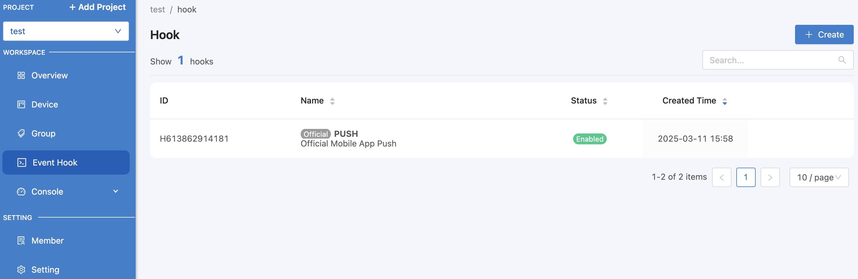
From the image above, you can see that there is an Event Hook list that is a default list that the system can call immediately. There will be a tag Official attached to it, which the user cannot delete. Currently, there is 1 Official Event Hook, which is PUSH, used for Notification via the Platform's Mobile Application. When clicking on the Event Hook list, it looks like this:
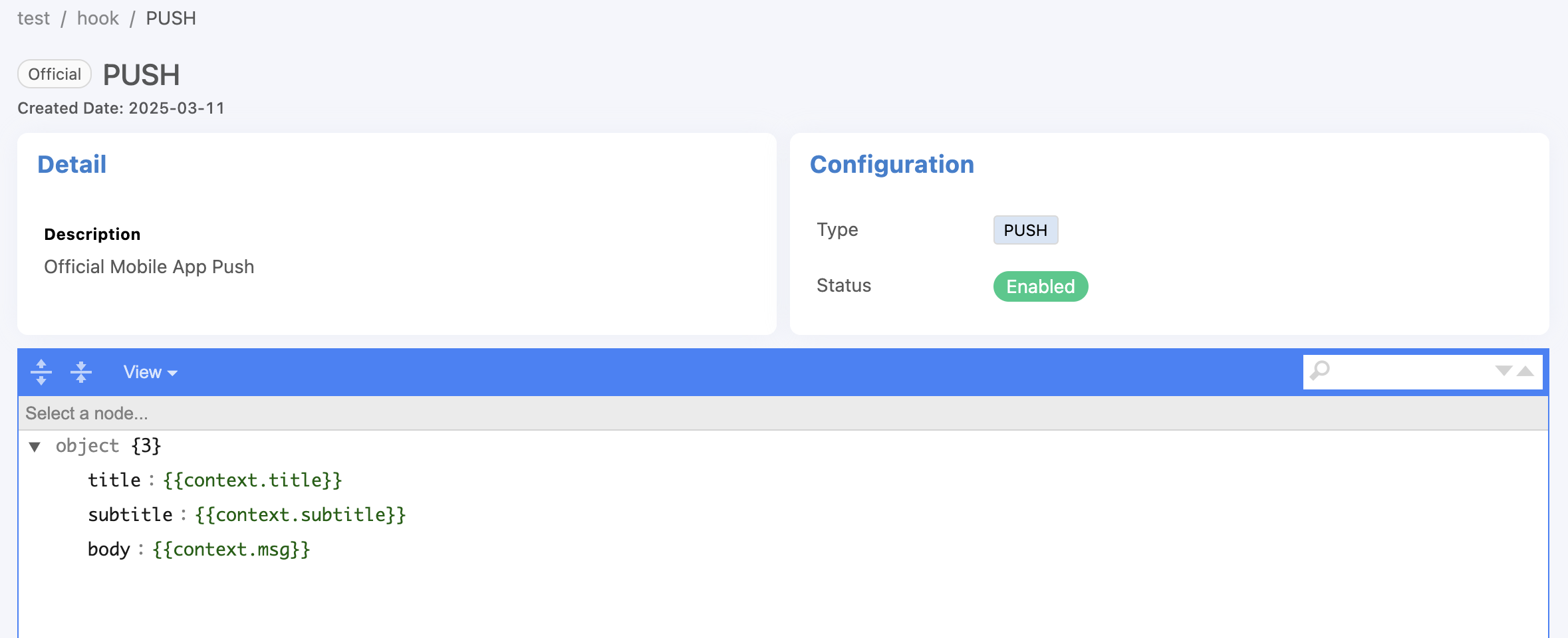
From the figure, there are 3 context variables: title, subtitle and msg that are received from the Trigger to replace the values. The context variable is in With this context variables in the Trigger and the reference value in the Event Hook is in the form {{context.variable_name_in_the_Trigger}} as shown in the following figure.
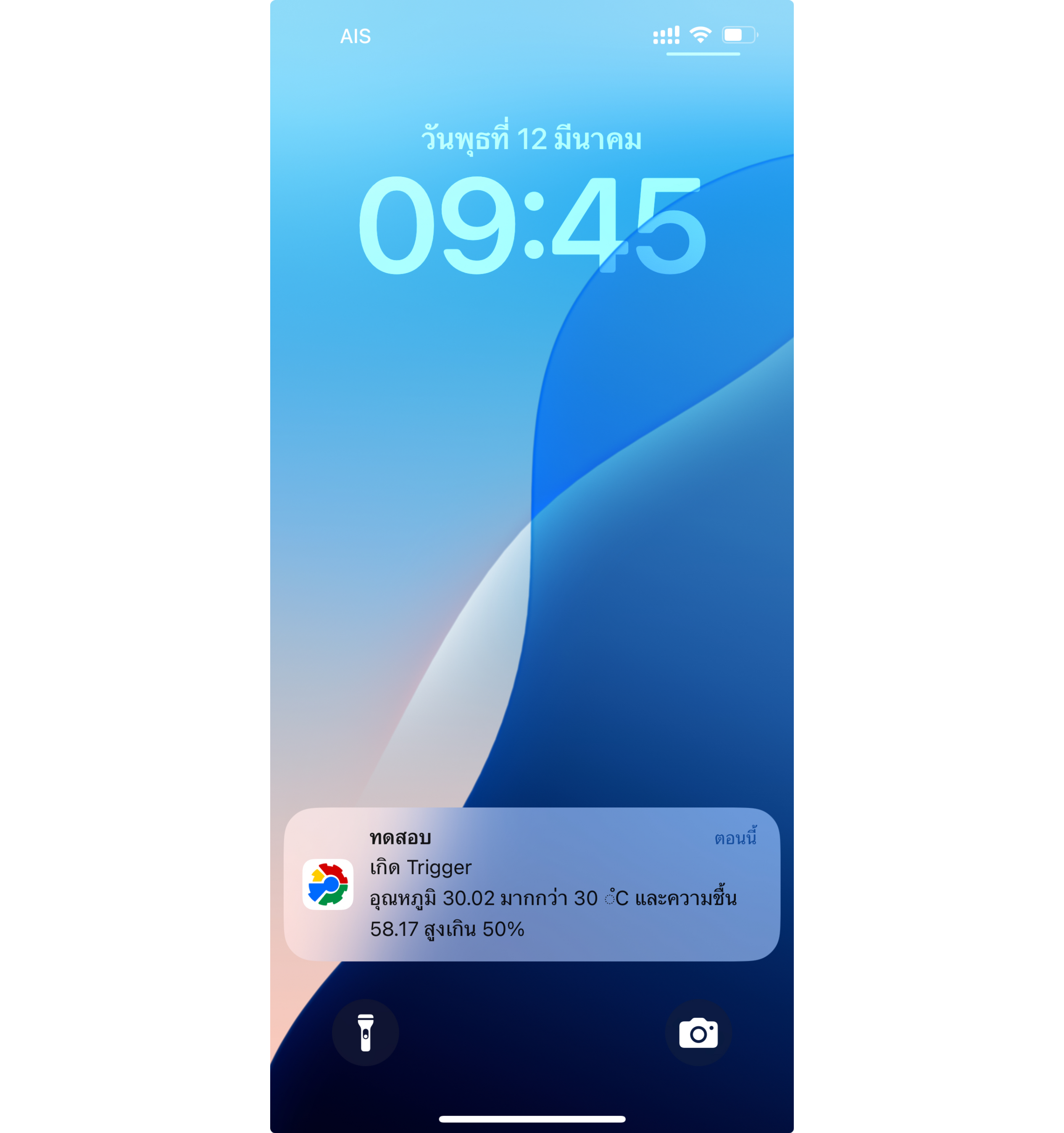
When the Trigger occurs and the Event Hook is set to PUSH as in the previous example, the display received from the Platform's Mobile Application will look like this.
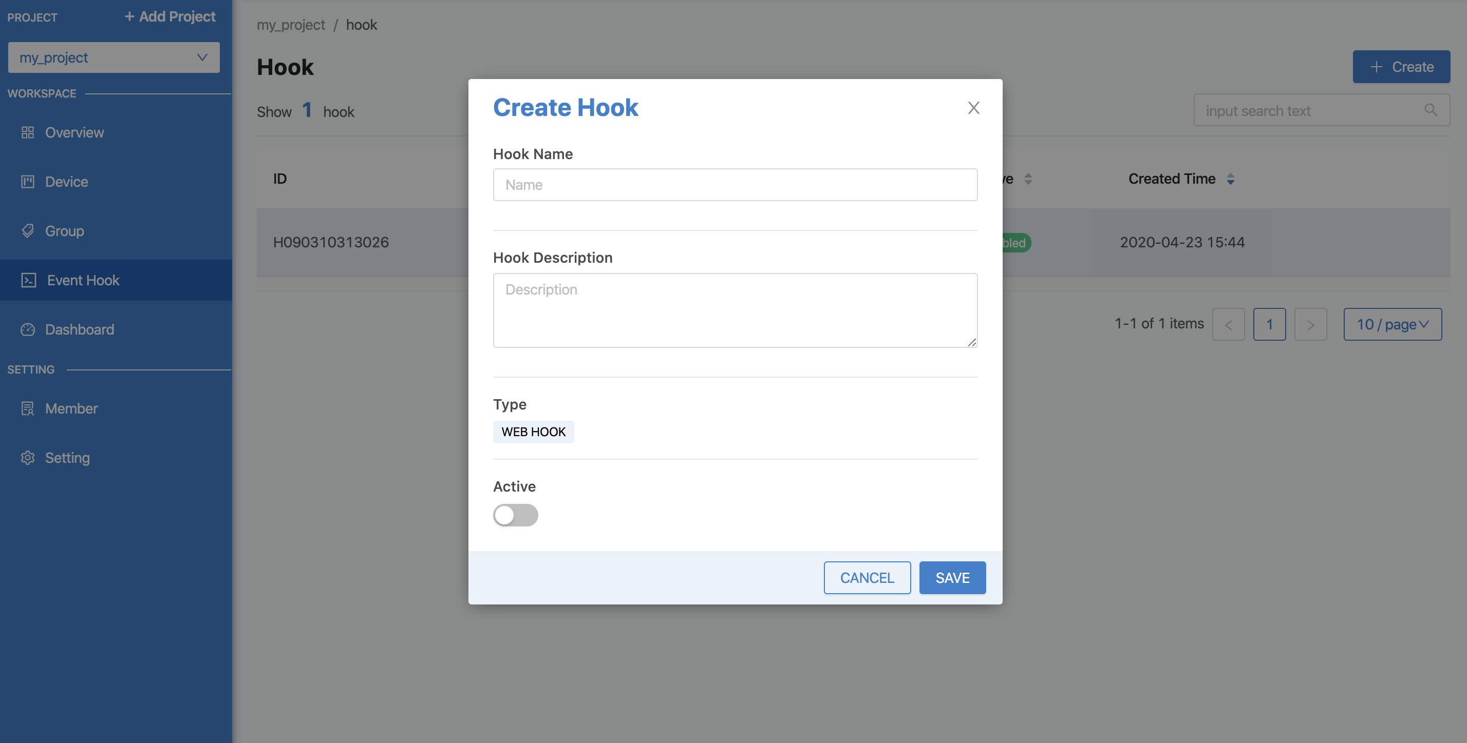
To create your own Event Hook, click the "Create" button, fill in the information for Type, which is the type of Event Hook. Currently, there is only one type, WEBHOOK. In the future, other types will be developed. Then click the "Save" button. The system will create the Event Hook as shown in the picture.
Then click on the created Event Hook item to enter the configuration settings. The configuration will be set in JSON format as shown in the figure.
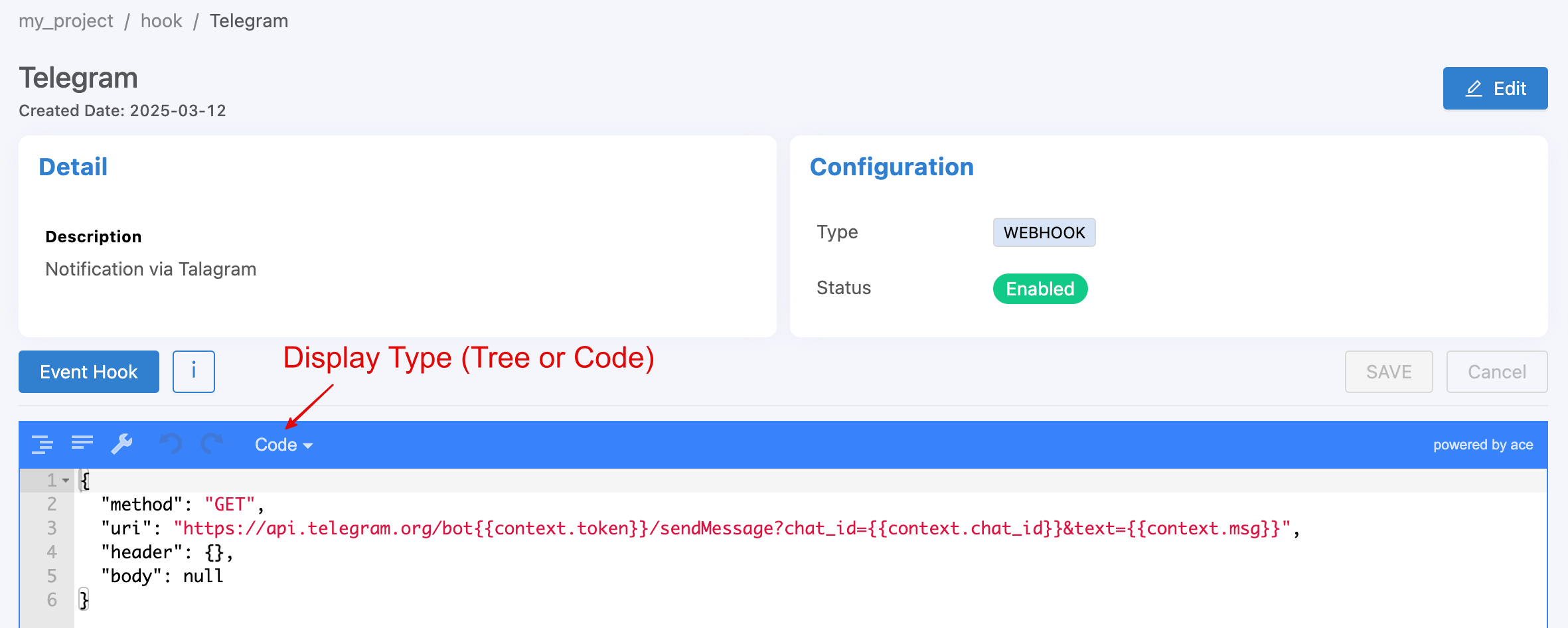
{
        "method": "GET",
        "uri": "https://api.telegram.org/bot{{context.token}}/sendMessage?chat_id={{context.chat_id}}&text={{context.msg}}"
}
From the example in the image above, the Event Hook will be set to send a notification message to Telegram (a messaging application similar to Line). The parameters for the value via Telegram's API have 2 Attributes:
methodis the part that specifies which method the destination wants to send it in: GET, POST or PUT, similar to HTTP Methods.uriEndpoint is the destination that specifies where you want it to be sent.
Note
Referencing variable data in Triggers and Event Hooks
It can be seen that there are 2 forms of variable references: those that must be enclosed and those that do not. This is because the types of data that the variables are referenced are different. That is, if it is a reference in a condition (Condition), the variable can be referenced without having to enclose the variable with {{...}}. However, if it is a reference in a text (String), it is always necessary to enclose the variable with {{...}}.
Device Feed/Datatag
To manage and view data in the Timeseries Database of each Device, which can be done through the Portal from the tab named Feed as shown in the following figure.
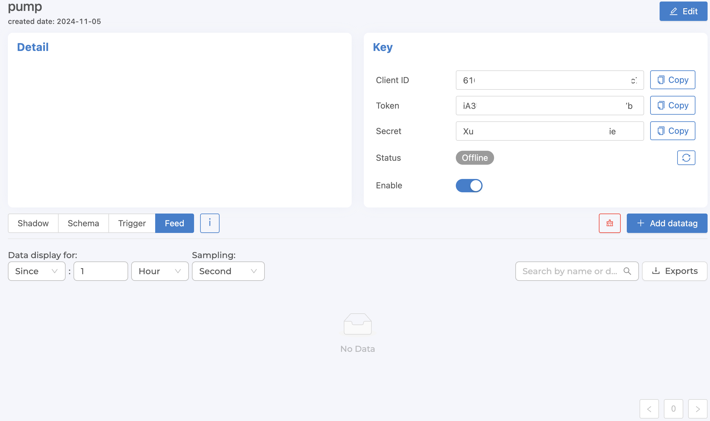
From the figure above, it can be seen that saving data to Timeseries Database must start from creating Datatag, which will be the part that connects to Shadow to define which Shadow field will store the value in Timeseries Database without having to define through Schema (original format). To create Datatag, click on the "+ Add datatag" button, the form will appear as shown in the following figure.
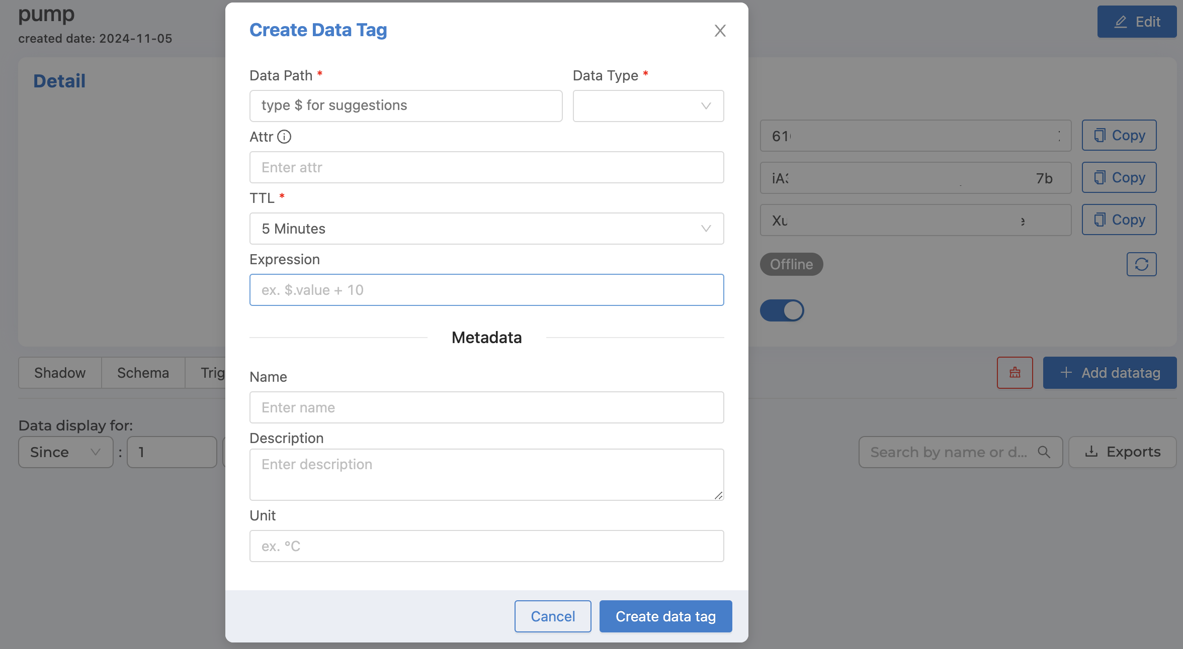
From the image above, the Datatag information that can be identified is as follows:
Data Path |
Fields in Shadow that you want to specify to be saved to Timeseries Database (enter |
Data Type |
Data type |
Attr |
New defined field name for easier reference to access values instead of referencing from Data Path. |
TTL |
Time-To-Live The duration of time you want to store data. When time passes, the data will be automatically deleted according to the set time. |
Expression |
Data conversion, such as converting from Celsius to Fahrenheit, can be done by entering ($.value * 1.8) + 32 in the Expression field, where $.value will be a reference to a value from the Data Path that is already specified, no need to reference it by name. |
Name |
Datatag name (If not specified, the system will automatically use Data Path as the name) |
Description |
Datatag Description |
Unit |
Datatag counting unit |
When you have filled in all the information, click on the "Create data tag" button. The system will create a Datatag based on the information entered, as shown in the picture.
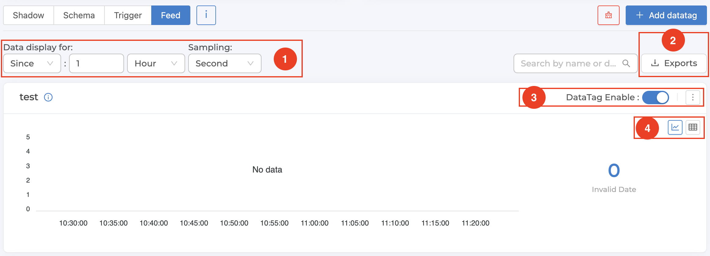
From the figure above, each Datatag management has several sections that can be operated. Each section has the following details:
1. Set the time range and detail of the displayed data
Sinceis a time period setting to display data from the present backwards. Enter an integer and select the desired unit. The system will automatically retrieve data according to the specified time period and display it.From - Tois the process of specifying the start and end dates for displaying the data. Select the date and time from the popup that appears. Once you have selected the date and time, click the "Ok" button in the popup. The system will automatically retrieve the data for the specified time period and display it.Samplingis to specify the resolution of the data to be displayed. For example, if you select "Minute", it means that in a period of 1 minute, the system will retrieve 1 value to display. In the case that multiple values are recorded in a period of 1 minute, the system will calculate 1 average value to use in displaying the results, etc.
2. Downloading data from the system (Export Feed)
This is to download data stored in Timeseries Database according to the specified time period into a .csv file. This can be done by clicking the "Exports" button. A popup will appear to set the data you want to download as shown in the image below. Once the settings are complete, click the "Download" button.
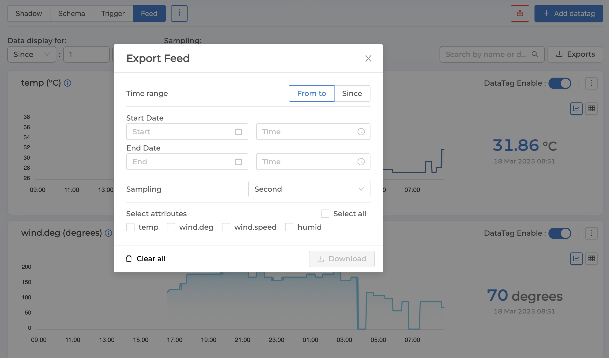
The settings that must be specified to specify the data to be downloaded are as follows:
Time range |
Time and detail of data to download (same as display settings) |
Select attributes |
Datatag to download |
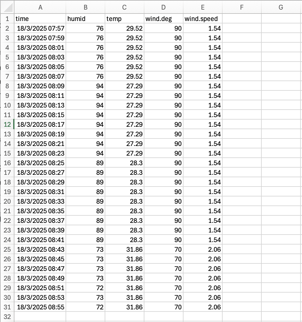
The downloaded data will be exported in a .csv file format as follows:
3. Datatag management
It is a section used to manage Datatags, located at the top right corner of each Datatag. Details are as follows:
DataTag EnableUsed to enable/disable the status of allowing values to be saved in Datatag.Edit datatag(Click on the three dots) to edit the Datatag settings.Clear feed(Clicking on the three dots) will permanently delete all data saved in Datatag.Delete feed(Clicking on the three dots) will permanently delete both the data saved in the Datatag and the Datatag from the system.
4. Type of data display
This is the section used to set the display format of each Datatag by clicking on the icon on the right corner of each Datatag. There are 2 types to choose from:
Graph (click on the graph icon) are best suited for displaying data with a Data Type of:
NumberTables (click the table icon) are suitable for displaying data of all types. And in case you want to edit/delete some data points in the Datatag, choose to display as a table and choose
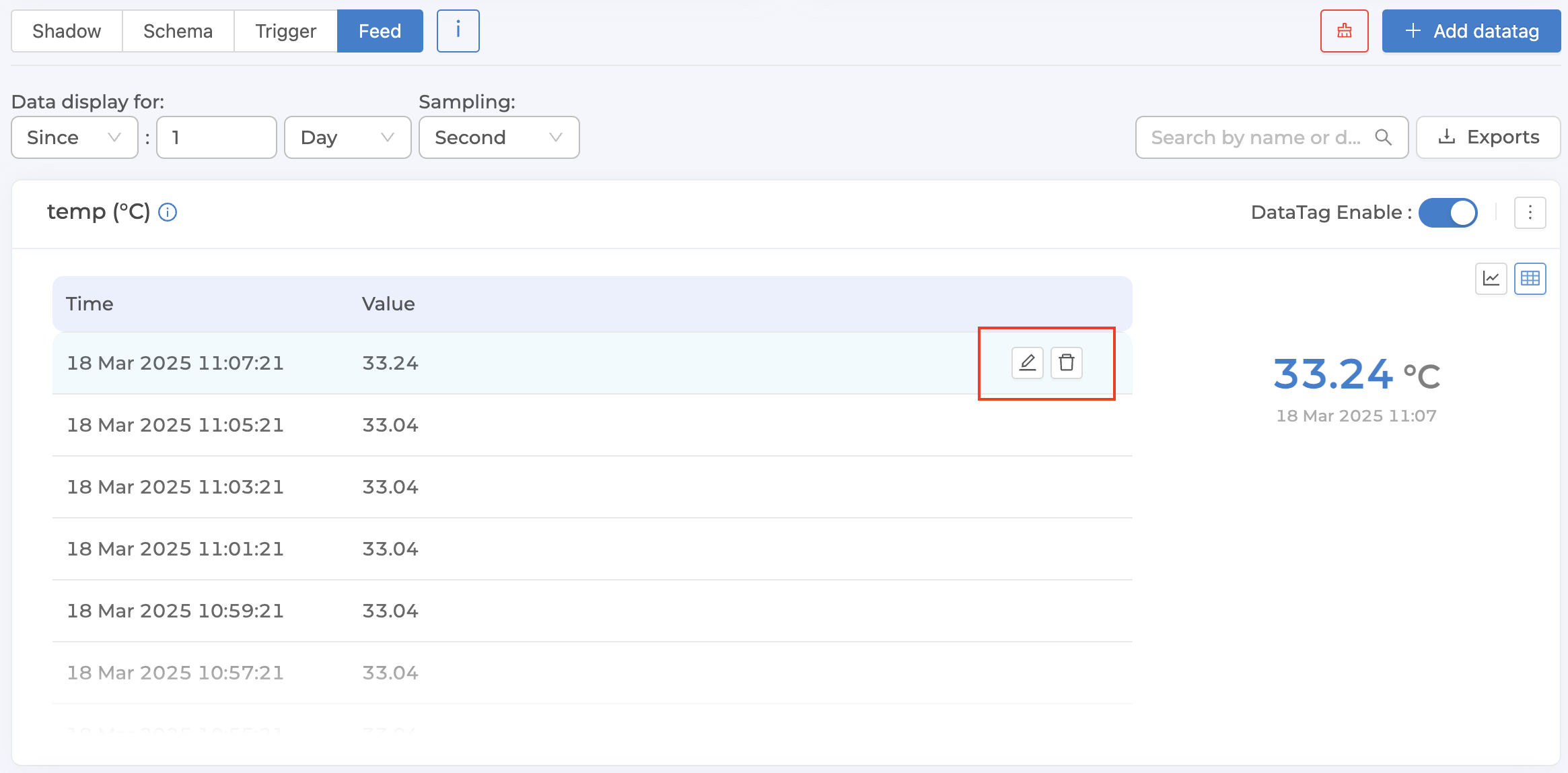
Samplingeach data point to be an actual data point, not an average point. After each data point, an icon will appear that allows you to edit/delete that data point, as shown in the following figure.
Warning
Precautions for setting up Feed
It is recommended to set the Data Type to match the data being saved to the Shadow, as the system will attempt to cast the value to the specified type. For example, the string "2" will be converted to the number 2. However, if the value cannot be cast — such as when the Data Type is set to
Numberbut the value being sent to the Shadow is14 June 2023— the system will not be able to convert the value and the data will not be saved to the Feed.The values saved to the Feed will be the values that have been processed by the Shadow. Therefore, if the Shadow has set an Expression to transform the value, the value received by the Feed will be the transformed value. There is no need to set an Expression in the Feed.
Deleting a Datatag will also delete the data in the Timeseries Database of that Datatag.
Note
Differences in Expression Definition in Datatag and Schema
Defining Expression in Schema can reference all values in Shadow to be calculated together. However, if defining Expression in Datatag, it can reference only one value as specified in Data Path and can only calculate constant values. It cannot calculate other values in the same Shadow together.
Note
The maximum number of data points that the system can retrieve at one time.
In extracting data from Timeseries Database for viewing or downloading data, the system limits the maximum number of data points to no more than 100,000, calculated from the amount of raw data before processing the data resolution according to the selected sampling and is the total count from all fields from which data is retrieved. If the retrieved data exceeds 100,000 data points, the system will automatically cut off the data. The data will be sorted from the start time to the end time selected for extracting data, and the excess data at the end will be cut off.